|
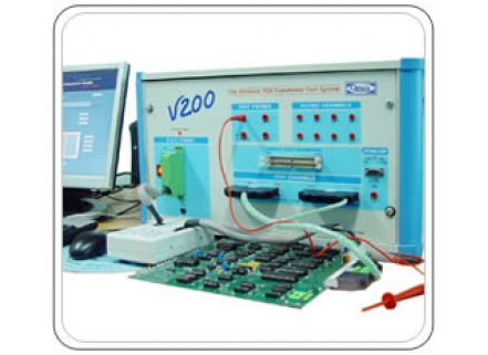
PCB Diagnostic Systems - Top ATE
V200 is designed as a Combinational Board Tester with Digital / Analog and Mixed Signal Test capabilities through simple clips and probes or through card edge or as a cluster tester with a special test fixture for up to 96 (Digital) 256 (Analog) test pins. In addition, it has the fully integrated Boundary Scan Test option for virtual pin test concept, where the number of virtual test pins has no physical limit. It’s has user programmable test speed and can generate test patterns at 10MHz data rate.
V200 can perform In-Circuit Functional Test, testing individual lCs in In-Circuit or Out-of-Circuit with Pin Status Check & has In-built DRC (Design Rule Checker). V200 Utilizes IEEE Standard VHDL language based device library for digital devices. For Analog / Mixed Signal Devices, Python TD Test languages based scripts are available for stimulus and output evaluation.
Auto compensation and Identify unknown or house coded devices are extended for all digital devices (not limiting to SSI/MSI) and thus LSI / VLSI chips can be tested / identified in its In-Circuit configuration without the need to learn / remove from a known good board.
V200’s QSMVI Stimulus for VI Trace can be used from available Standard or from user defined wave pattern, thus not limiting the VI trace to simple sine wave alone. User defined wave pattern can be any mathematical wave Shape such as sine / triangle / square / ramp or even arbitrary patterns as desired by user and can be stored in the Library for possible re-use. The frequency is fully programmable from as fast as 100 KHz as a result of V200's vast time base selection capability.
"Best Fit Curve" - a unique feature, where the best drive pattern is automatically suggested to the user for the characteristics of the UUT to increase the fault coverage with advanced algorithm suggests the failing pin within A device with% probability.
V200 can perform Resistance, Inductance, Capacitance, Voltage and Frequency Measurement along with 3 Channel - 10Mega Sample Scope with Programmable Load and 3 Channel Function Generator. V200 with TD6 Test Sequencer software allows Sequencing of multiple test using combination of isolated device test (ICFT), QSMVI, Measurements, Card Edge Functional Test, Integrated Card Edge +Boundary Scantest ', all in one test program.
Test Sequencer Software allows graphical TPS development using JPEG image of the PCB under test, tagging devices and pins. Adding tests to the devices, cluster is with just a right click of the mouse. Learn, verify and test options using mouse click on the device location.
Using V200 Card Edge Functional Test for complex boards with ASICs and BGAs, where no functional data are available, user can generate the test vectors using the graphical waveform editor or Python TD test vector generator, where the primary IO pins can be either physical edge pin or In Circuit pin or a JTAG Virtual Boundary Scan Pin. User can either learn the expected output from a known good board or define the expected output using graphical waveform editor or simulate the expected output using VHDL Simulation or the Python TD test language with mask or tolerance editing facilities. Test program developed can be used for a device or cluster or a complete PCB.
| Features |
Features
• V200 is designed as a Combinational Tester with Digital / Analog and Mixed Signal Test capabilities
through simple Clips and probes or through card edge or as a cluster tester with a special test fixture
for up to 96 digital test pins and up to 256 analog test pins and un-limited virtual test pins using
Boundary Scan Test.
• Its basic timing unit is 100ns and thus can generate test patterns at 10 MHz data rate.
• The timing units are programmable in 2000 steps from 100ns to 200µs, (100ns, 200ns, 300ns etc up
to 200µs) thus allowing accurate pattern timings.
• It has 8K X 4 RAM behind each digital pin electronics and 8K X 24 RAM behind every analog channel.
• Its advanced sequencer allows external event synchronization or handshake, which are very essential in
complex microprocessor tests. Functional Test facility for testing individual ICs in In-Circuit or Out of
Circuit.
• Pin Status Check & In-built DRC (Design Rule Checker).
• IEEE standard VHDL language in behavioural description of the function of the chip in its library.
• PythonTD Test language for Analog / Mixed signal device stimulus and output evaluation.
• Auto compensation is extended for all digital devices ( not limiting to SSI / MSI ) and thus LSI / VLSI
chips can be tested in its in-circuit configuration without the need to learn from a known good board.
• High current rating and five voltage output options for the Board Under Test with latest SMPS module
(450 watts).
• Qmax Fault Simulation validated vast Device Library of > 33,000 devices.
• Clock Terminator feature avoids false failures while testing state machine devices such as flip-flops and
counters thus increasing productivity.
• Auto In-Circuit compensation.
• Auto Guarding Guide for Bus based devices and OC / OE Devices.
• Logic analyzer waveform display for failure confirmation.
• Identify Unkown and House Coded devices including LSI devices with advanced foot print match
algorithm.
• Graphical test program generator for Digital, Analog, Mixed signal devices. Mixed logic testing through
dual palettes.
• Automatic internal pull-up/down for open collector and open emitter devices.
• Automatic Guided Probe Back Tracking for Fault Isolation up to node level. User defined Error Log
reporting. Failure analysis, statistics and datalog. Fault Simulation for card Edge Test
• Program and Library Device Programs.
• Fault Dictionary Data Base.
• QSM VI – a unique analytical tool to troubleshoot faults on Hybrids/Custom ICs as well as ESD damaged
devices.
• “Best Fit Curve” algorithm in automatic selection of source impedance, frequency and amplitude of the
VI stimulus signal for maximum fault coverage.
• Dual trace facility for probes and clips.
• User defined wave pattern as stimulus for VI Trace and thus not limiting the VI trace to simple sine
wave alone.
• User Defined Wave pattern can be any mathematical wave shape such as sine / triangle / square /
step / ramp or even arbitrary patterns as desired by user and can be stored in the Library for possible
re-use.
• The frequency is fully programmable from as fast as 100 KHz (100 samples per cycle) down to 1 Hz
due to V200's vast time base selection capability.
• User programmable amplitude, source impedance and frequency.
• Use of Step wave is useful in analyzing transient response of node.
• Incorporates Interactive mode as well as learn and compare.
• Fixed Reference, any pin to any pin or user combination.
• Frequency measurement up to 50 MHz.
• 3 channel Digital Oscilloscope with programmable load and Function Generator .
• Board Learn/Compare mode results in increased board recovery rate.
• Interactive, TestSequencer and TestStation Software package – TD6.
• Optional Circuit Tracer for schematic generation / reverse engineering applications.
• Optional IDDE software for easy Device Test Program Generation with Fault coverage report.
• Optional Russian Device Library & Military part code library.
• Resistance / Capacitance / Inductance Measurements.
• Diode Measurements.
• Frequency Measurements.
• Period / Time Measurements. |
|