

INSTRUEMENT PRODUCTS |
BROADCAST PRODUCTS |
COMMUNICATION PRODUCTS |

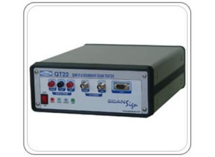
QT22 VI
|
||
|
PCB Repairs - BS Controller Overview Today’s PCBs are complex in nature and with more of proprietary devices. In most cases, the schematics and internal functional details are unavailable for third party maintenance personnel. As a result diagnosing PCB faults using conventional test instruments such as multi-meter or oscilloscope, which are normally found in repair shops, becomes a difficult task. Test Program development for Automatic Fault Diagnosis using even high end ATE systems become impossible task.
QT-22’s QSM VI can detect a change in Boards/devices pin characteristics due to a damage caused by external forces such as lightening, Static discharge, Short circuit / over loads and value change in discrete components. In QSM-VI Signature test method, the KGB’s VI traces can be learnt and stored for future reference. The system uses probe & reference for comparison of each node (or) interfaces to an automated Robotic arm with multiple probes for high density board probing without a bed of nail fixture. Best Fit Curve Qmax has developed an advanced algorithm based Automatic “Best Fit Curve”, which selects the Voltage, Source impedance and frequency of the VI stimulus signal depending upon the test node and its characteristics. For example a test node had a diode, resistor and capacitor in parallel, the system learns a VI Curve using high voltage to detect the presence of diodes / Zenors, a low voltage typically 100mV to learn the resistance characteristic with a suitable source impedance, usually source impedance equal to that of the test node’s resistance value and another trace with higher frequency to detect the presence of reactance such s capacitor / inductor. Thus the system learn 3 traces with different set of Voltage, Source impedance and Frequency, This will help to detect even if any one of the component is missing or value changed. Another test technique which is gaining popularity is IEEE 1149.1 Boundary Scan Test Technique. As most of the devices of today’s technology comply with IEEE 1149 Boundary Scan, it becomes possible to test most ASIC devices, BGA packages and high density devices even though no data sheet or internal functionality is unknown. QT-22 offer this test technique which can be used for Scan chain detection, Device code read, user code read, interconnection between devices (solder check),integrity of the board & device and edge connectors using s simple 4 wire JTAG interface.
|