|
Overview
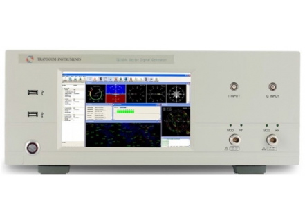
Transcom Vector Signal Generator T3260A is a high performance signal generator with frequency range 250KHz to 6GHz and 160MHz wide RF modulation baseband. It generate various radio system signal format for testing both analog and digital communications systems. The flexibility allow customer to customize its own special standard according. With the Satellite Signal option, the T3260A transform to a Satellite vector signal generator. For its dual independent signal generator output, it can simulate world command satellite signal such as BeiDou/ GPS/GLONASS/GALILEO and interference signal
| Key Features |
- High performance CW outputs( 250kHz to 6GHz/0.01Hz resolution)
- High accuracy amplitude output( -120dBm to +20dBm/0.01dB resolution)
- Wide modulation bandwidth(supporting LTE-A 100MHzand 802.11ac 160MHz bandwidth)
- QPSK digital modulation
- 3GPP TD-LTE signal output
- Analog I/Q inputs
- Support BeiDou/GPS/GLONASS/GALILEO
|
| Specification |
-
| Frequency Specification |
Frequency Range |
Frequency Range
Min Frequency
Frequency resolution |
250 kHz – 6 GHz
250 kHz
0.01 Hz |
|
Frequency switching Time |
CW mode
Sweep Mode
Digital Mode
SCPI Mode |
ALC on
ALC off
≤ 8 ms
≤ 8 ms
≤ 8 ms |
≤ 8 ms
≤ 100 µs |
Clock Accuracy |
Internal Clock Accuracy
Internal Reference Output
External Reference Input |
Aging Rate
Resolution
Temperature Stability
Line Voltage Effects
Frequency
Amplitude
Impedence
Waveform
Frequency
Amplitude
Impedence
Waveform |
<±2×10⁻⁸/yr
<5×10⁻⁸
<±3×10⁻⁹/yr(-40° ~ +80°
<±0.3×10⁻⁹/yr(±5%)
10MHz
+2dBm ~ +6dBm
50Ω
Sine
10MHz
-15dBm ~ +5dBm
50Ω
Sine/Square |
| Sweep Mode |
Working Mode
Step Range
Sweep Range
Dwell Time |
Single Sweep
Cycle Sweep
±(0.01Hz ~ 3GHz)
same frequency range as the instrument
100μs ~ 100s |
|
| Spectral Purity Specifications |
Absolute SSB Phase Noise
(dBc/Hz )(@20kHz)
(10dBm) |
≤250 MHz
250.1 MHz
500 MHz
1 GHz
2 GHz
3 GHz
4 GHz
6 GHz |
-124
-136
-130
-124
-118
-115
-112
-109 |
Harmonics
(CW, <+4dBm) |
250 kHz – 1 MHz
1 MHz – 10 MHz
10 MHz – 250 MHz
250 MHz – 500 MHz
500 MHz – 3 GHz
3 GHz – 6 GHz |
< -30 dBc
< -30 dBc
< -40 dBc
< -30 dBc
< -35 dBc
< -30 dBc |
Non-Harmonics Spurious
(CW, >10kHz) |
250 kHz – <10 MHz
10 MHz – <250 MHz
250 MHz – <750 MHz
750 MHz – <1.5 GHz
1.5 GHz – <3 GHz
3 GHz – <6 GHz |
< -40 dBc
< -45 dBc
< -65 dBc
< -65 dBc
< -70 dBc
< -70 dBc |
Sub-Harmonics
(CW, >10kHz) |
250 kHz – <10 MHz
10 MHz – <1.5 GHz
>1.5 GHz – < 3GHz
>3 GHz – 6 GHz |
< -50 dBc
< -65 dBc
< -60 dBc
< -40 dBc |
| Amplitude Specifications |
| Output Parameters |
Output power setting range
Level Resolution
Attenuator
Connector |
-120 ~ +15dBm
0.01dB
0 ~ 100dB,10dB step
N type,50Ω |
| Maximum Output Power |
250kHz ~ 1MHz
>1MHz ~ 10MHz
>10MHz ~ 250MHz
>250MHz ~ 1GHz
>1GHz ~ 4GHz
>4GHz ~ 6GHz |
0dBm
+8dBm
+10dBm
+15dBm
+15dBm
+13dBm |
Absolute amplitude level accuracy in
CW mode
(ALC ON) |
Amplitude
10MHz ~ 250MHz
>250MHz ~ 4GHz
>4GHz ~ 6GHz |
+15 ~ -60dBm
±0.8dB
±0.6dB
±0.8dB |
<-60 ~ -100dBm
±1.0dB
±0.9dB
±1.1dB |
<-100 ~ -120dBm
±1.3dB
±1.5dB
±2.0dB |
| SWR (@ CW mode) |
Amplitude
≤1GHz
>1 ~ 2GHz
>2 ~ 3GHz
>3 ~ 4GHz
>4 ~ 6GHz |
+15 ~ -20dBm
<1.3
<1.44
<2.0
<2.0
<2.0 |
< -20dBm
<1.3
<1.44
<1.3
<2.0
<2.0 |
| Maximum reflected Power |
100k ~ 6GHz
Max DC Voltage |
1W
50VDC |
| Amplitude Switching Time |
CW Mode
Digital Mode ON* |
ALC on
ALC off
SCPI Mode
ALC on |
≤8ms
≤10μs
≤8ms
≤8ms |
| |
|
|
|
|
|
|
| Analog Modulation Specifications |
| Frequency Modulation |
Frequency Swing
Resolution
Carrier Frequency Accuracy |
|
| Amplitude Modulation |
Max Modulation Depth
Modulation Depth Resolution |
|
| Internal Standard Simulator |
Waveform
Frequency Range
Resolution
Frequency Accuracy |
Sine(AM、FM)triangle/square/sawtooth(FM)
1Hz ~ 10kHz
0.1Hz
same accuracy as the RF source |
| Phase Modulation |
On/Off Ratio
Raise/Fall
Min Phase Bandwidth (ALC off)
Repeat Frequency Rate (ALC off) |
<4GHz >70dB
>4GHz >60dB
<200ns
>2μs
DC ~ 250kHz |
| Internal Phase Generator |
Mode
Square Rate
Period
Phase Bandwidth
Resolution |
Square
1Hz ~ 250kHz,Resolution:1Hz
4μs ~ 1s
2μs ~ 1s
2μs |
| Vector Modulation Specifications |
| External IQ Input |
Max Bandwidth
Full Scale Input drive |
0.1 ~ 160MHz
0.5V,50Ω |
| I/Q Baseband output |
Impedance
Type
Maximum Voltage per Output
Bandwidth
Common mode I/Q offset |
50Ω
Single end or Differential
±0.5Vp-p
0.1 ~ 160MHz
0V |
| Baseband generator |
Channels
Resolution
Sample rate
Max RF bandwidth |
4[I+/I- and Q+/Q-]
16 bit
400MSa/s
0.1 ~ 160MHz |
| Arbitrary Modulation mode (ARB) |
Modulation
Symbol Rate
Filter
Data Types |
BPSK、QPSK、16QAM、64QAM
0.1 ~ 160Msps
RRC、RC
Pseudo-random patterns |
EVM Specification
(Channel corrections off) |
Standard
Modulation
Modulation rate
Frequency Range
EVM Power level
EVM
EVM
Modulation rate (RRC, α=0.25)
Frequency
EVM Power level
EVM |
LTE-TDD |
| QPSK |
| 15 MHz |
20 MHz |
| 1.8 ~ 2.2GHz |
1.8 ~ 2.2GHz |
| ≤7dBm |
≤7dBm |
| ≤1.2% |
≤1.5% |
| QPSK |
| 4Msps |
10Msps |
| ≤4GHz |
≤4GHz |
| ≤4dBm |
≤4dBm |
| 1.2 % |
1.2 % |
| General Characteristics |
| Front Panel Ports |
RF Output
I/Q Ubput
USB |
N-female, 50Ω
BNC,50Ω,Max. 1Vp-p
3 x USB 2.0 Type A |
| Rear Panel Ports |
I/Q Output
AM
FM
Pulse
REF IN
REF OUT
VGA
USB(A)
USB(B)
LAN |
BNC,Analog baseband I /Q data output,
Impedance 50Ω
Ext. AM Input,BNC/50Ω
Ext FM Input,BNC/50Ω
External pulse modulation input; this
input is TTL and CMOS compatible;
BNC/50Ω, nominal low level is 0V, and
high level is +1V Low Level 0V,High
level +1V
Accepts a 10MHz reference signal used
to frequency lock the internal time
base; nominal input level 0 to 20dBm,
50Ω, sine or square waveform wave
Outputs the 10MHz reference signal
used by internal time base; level
5dBm, 50Ω
Ext Monitor
Connect to external peripherals
Remote control connection |
| Interfaces |
Interfaces
Control language |
LAN
SCPI 1997.0 |
| Power requirements |
220 ~ 240VAC,50/60Hz,300W |
| Operating Temperature range |
0 ~ 40℃ |
| Storage Temperate range |
-10 ~ 55℃ |
| Weight |
≤18.5kg |
| Dimensions |
176mm H ×420mm W ×520mm L |
|
|